NEWS ARTICLE ARCHIVESPump Installation Calculations from Kelair Pumps Australia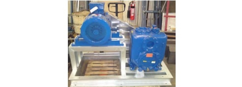
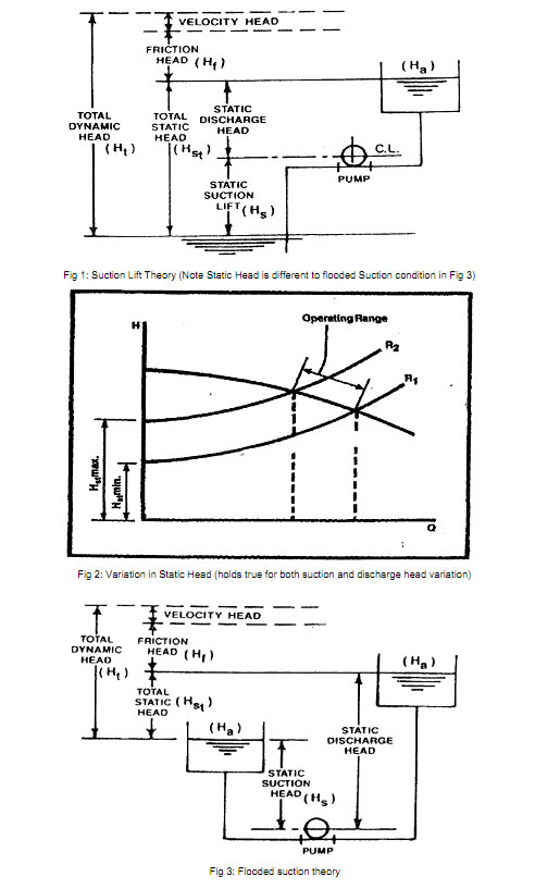
Case Study Kelair plots a curve to solve old centrifugal pump problem Recently, one of Kelair's customers contacted us regarding replacement of an old centrifugal pump which was being used in a suction lift application for water. There were no pump curves available for the existing pump as it is now considered obsolete. We knew the pump's dimensions, and the customer also had a pressure gauge fitted at pump discharge. We also had the necessary pipework data for the existing installation. Two things the customer did want were a higher flowrate, and additional 2 metres suction lift (totalling 4 metres lift). They anticipated the flow was in the vicinity 35 LPS and wanted a 25% or so increase to 45 LPS. However, those flowrate figures were just estimates. They couldn't even measure volume of water transferred, to time how long it took, as water at suction was from a reservoir, and the discharge tank had equipment (of unknown volume) in it. That's where Kelair Pumps come in. The engineers we work with; the plant engineers, consulting engineers, maintenance personnel etc are experts in their field. It's our responsibility to be the experts in pumps and pump installation calculations. We were given duty pressure of 380kPa when suction lift was 1 metre, and shutoff head of the existing pump was 600kPa. What could we ascertain from this available data? Not only could we advise what the existing flowrate was (it was actually about 35% less than they had anticipated), we could also plot a pump curve for the obsolete pump, and this curve would incorporate power and even an 'indication' of efficiency. Then we were able to offer a new pump, a Pioneer self-primer heavy duty pump, capable of handling 4 metres suction lift, and also capable of 25% increase in flowrate, all with the same size motor. Where did we start? By looking at ISO pump curves. A size 100x65- 200 at 2900rpm gave an indication that the estimated flowrate and pressure was achievable with an 18.5kW motor, at 70% efficiency. However, there was a problem. The existing pump was only 3x2-9 (equivalent to 80x50-200 in metric), not a 100x65-200. When we looked at the ISO 80x50-200 it couldn't even generate 35 LPS. Maximum flow at end of curve was 27.5 LPS with an 18.5kW motor. So here we got an indication that the existing pump may not be able to generate that sort of flowrate. But that's an indication only, not confirmation, as different pump specs (ISO, ANSI, DIN, API etc) can yield very different pump curves. The next step was to generate a system resistance curve for the existing system. (This is where we get into pump theory for those who are interested in the finer detail) We knew where the system resistance curve would intersect the "Discharge Head" axis (the vertical axis), because we had the static suction and static discharge head. We had a 3 metre fluctuation with static suction head which meant that the system resistance curve would rise or fall by 3 metres on the vertical axis. (Refer Fig.1, which creates the curves shown in Fig.2). Now 3 metres may not be very significant in this instance, but if you have a suction tank or a discharge tank that varies by 10 to 20 metres, it would certainly be significant. Did you know that when Static Flooded Suction Head is greater than Static Discharge Head, the system resistance curve starting point begins below zero? (Refer Fig.3). When we began to review the pipe friction handbook, we noticed that if the flow had been 35 LPS, it would have already been at the maximum recommended pipe velocity stated by the Pump Manufacturer's Association which would have meant that the requested 45 LPS was way over the recommended limit. Plus our calculations showed us that the discharge pressure would have been 650 kPa at 35 LPS, when in reality it was only 380kPa at that flow. Once we plotted the system resistance curve, we discovered that the actual flowrate was 21 LPS at 380 kPa, based on 1 metre suction lift. So we were able to generate some very useful information. As an aside, at that flowrate, the ISO 80x50-200 at 2900rpm, could achieve 580 kPa at 75% efficiency with an 18.5kW motor, or 480kPa at 72% efficiency with a 15kW motor. This showed us that the existing pump was probably only operating with significantly reduced efficiency, possibly somewhere in the vicinity of 60%. Plotting the (estimated) obsolete curve was just a matter of joining two points, that is shutoff head, 600kPa at zero flow, and the other duty point being 21 LPS at 380kPa. We could estimate the obsolete power curve because the existing 18.5kW motor would have been selected to end of curve power (which we could confirm by current draw if we needed to). So end of curve power would be anywhere between 15kW and 18.5kW, and efficiency at the duty point around 60%. Thus by understanding how to use the available data, we were able to ascertain all we needed (and more). The Pioneer pump we selected will run at 26 LPS to 28 LPS, which is 25% more than the actual flowrate as was requested. The small variation in flowrate would be due to the variation in suction head as stated above (and shown in Fig 2). Suction lift capability of 1 metre to 4 metres is easily achievable for the Pioneer when the existing centrifugal with foot valve on suction would struggle with 2 metres suction lift. And there would be no more after-hours call to re-prime the pump, as the Pioneer can re-prime itself if necessary. Again, as an aside, the Pioneer still only required an 18.5kW motor, the same as the existing pump even though flowrate had been increased by 25%. The Pioneer is 65% efficient at that duty, again confirming the lower efficiency of the previous pump. We are sure the customer will be very happy once he installs his new Pioneer self-priming pump.
|
 |
 |
Home | About/Services | News Lounge | News Archive | Product Archive | Tender News | Testimonials | Conditions of Use | Privacy Policy
![]()
![]()
![]()
![]()
© 2022 SPEC-NET